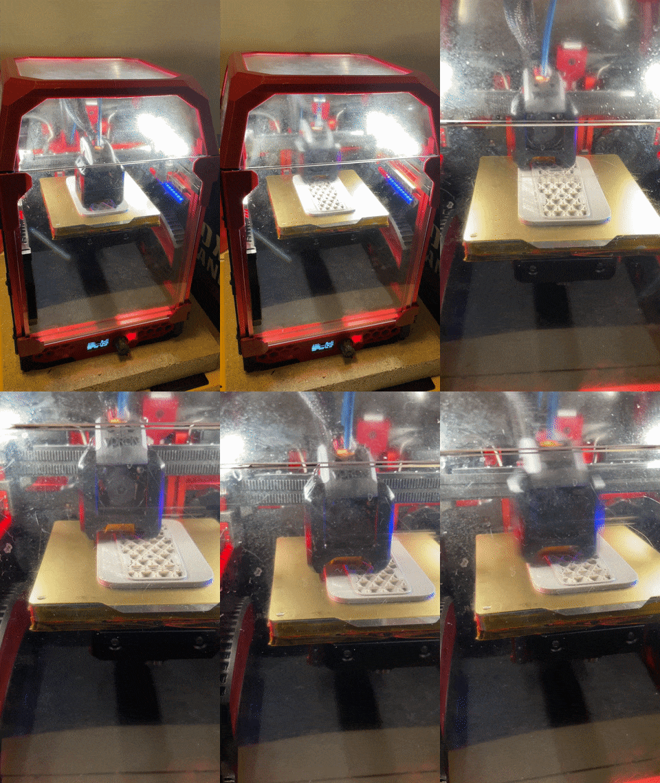
PROJECT_VORON_V0.165
Voron is an open-source project aiming to develop the fastest and the most capable FDM 3D printer.
V0.165 is the very specific model that I built using Voron V0 design and is publicly registered.
This blog will not dive into explaining how I built the V0 and how it works, but will rather show my own modifications and designs based on it.
You can learn more about Voron V0 and CoreXY here:
AUTO_LIGHT system
AUTOLIGHT is a Klipper macro that aims to automate adjusting the case light in the system.
Since Klipper (the firmware that is running on the printer) doesn’t support generic_ADC devices. One would have to hack a generic_thermistor module, in this case, it’s the ADC_Temperature module.
A thermistor works essentially the same as a photocell sensor because they both react to change in environmental conditions with change in resistance
Resistance ranges from ~500 Ohms in direct sunlight to ~5K Ohms in a lit room, and in excess of 50K Ohms in the dark.
A photocell sensor is an analog sensor that responds to the change in ambient light with a change in its resistance.
The SKR E3 mini V2.0 board that V0 uses has ADC pins as well as pins with pull-up resistors on them. Using an ADC pin would make this process a lot easier because you would just need to input the resistance values at 3 different stages into the Klipper module to plot out the brightness vs. resistance graph.
But I am lazy to do the wiring for an ADC pin so I just did it the hard way using a pin with pull-up and some math.
I won’t show you the exact math I did because I don’t remember them and you probably don’t care either. So here is the juice part:
What you would need to do in printer.cfg is to specify an ADC_Temperature module to represent our photocell sensor. I mapped the brightness value to 0-100 because that just makes sense.
Then you just need to declare the sensor object with the pin you plugged the sensor to, specify a wide temp range just to make Klipper not freak out when it goes out of the 0-100 range.
The mount is very simply designed, it uses a 2 parts chassis that house the photo cell sensor with a self tapping screw holding the 2 parts together. There is a printed clip on the side that mounts the chassis to the frame.
I installed 2 of those sensors on both sides of the printer. in the case one of the sensors gets blocked, we will only read the one with a higher value. I wrote this macro to map the sensor value to the case light brightness so that the brighter the ambient light the dimmer the case light will become.
Using the delayed_gcode module to call for the AUTO_LIGHT macro and itself every 30 seconds. So it executes the AUTO_LIGHT macro every 30 seconds to auto adjust the case light brightness based on the current ambient light brightness and repeat.
Neopixel_RGB Side_Bar
The idea of the Neopixel sidebar project is to utilize the Neopixel.py module in Klipper and potentially use that to create functions and animations that make the printer look cooler.
In this instance, I was able to make the LED sidebars displaying the progress of the print using colors.
The light bar I was using is this:
https://www.adafruit.com/product/1426
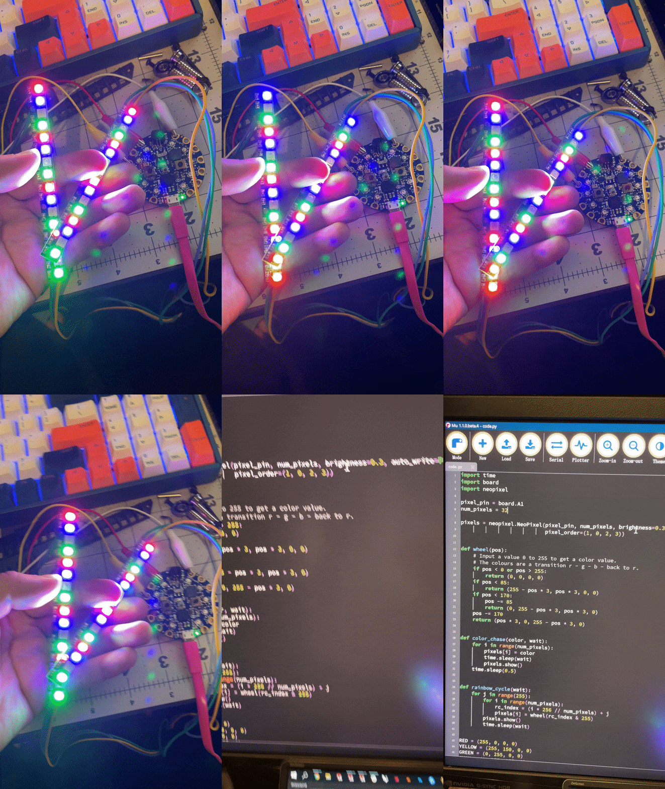
It features 5 x 5050 RGB LED with Integrated Drivers, you can control the individual RGB LED as well as each individual 3 color nodes inside it.
Here is a test using a Circuit Playground Bluefruit board and an example code to make sure that they work.
Here is the mounting bracket that I designed for 2x RGB sticks, one needs to solder the 2 boards together to essentially chain up the neopixel arrays.
By designing a clip, I was able to easily mount the bracket on the frame of the printer.
I designed an array of fins that blocks the LEDs from directly shining into your eyes. This bar will be mounted perpendicular to the front door.
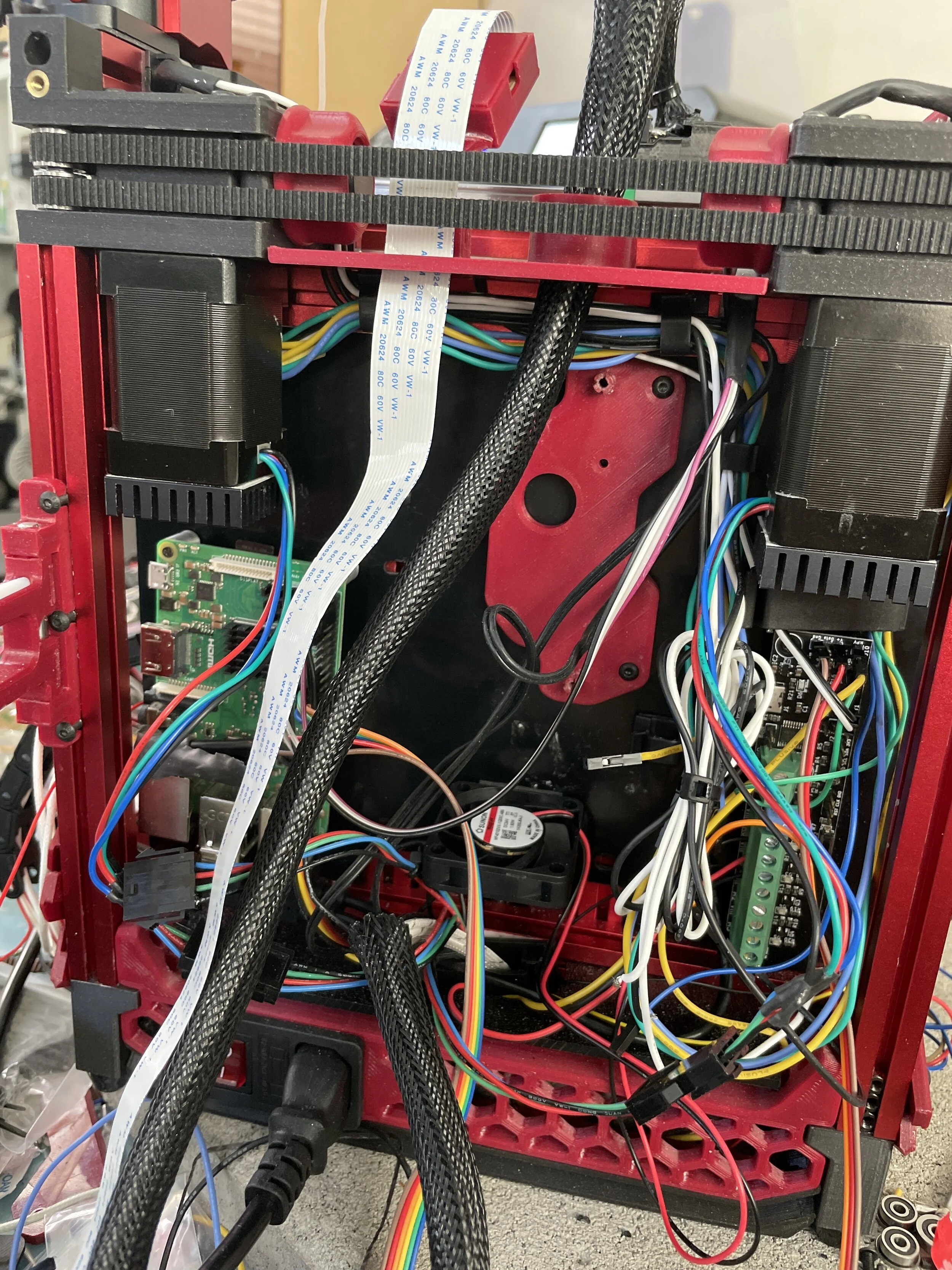
The wires go pass the rear panel and connect to the Klipper expander board on the deck.
Here is the code that runs the Neopixels:
First, you need to declare the neopixel object and name it to something you want.
This part of the code is the print progress display code. M73 is a marlin G-code that gets inserted into the G-code file by the slicer, it usually shows in a form as “M73 P{0-100%}. What my g-code macro is doing is that it will get called every time the M73 is being used as the MCU is processing the G-code file (during a print). The macro will interpret the number that comes after “M73 P” and use that to control the amount of pixel we want to show.
In addition to that, we want the LED array to show an even finer detail of the print progress because using 0-32 to map 0-100 is not very accurate. Therefore, I also managed to incrementally change the color of the particular pixel that is waiting to be transformed from one color to another as the print progresses.
To be specific, each pixel only changes as the print progress increase by 3 (100/32≈3). The array of pixels wouldn’t do anything during that 3 percent. But in order to display a finer detail of the print progress, I mapped the change within that 3 percent into the slow change of color from blue to red.
You can also do a simple flashing animation using a “for loop“.


![[(@R9CF@YFKY10]44XNB5HY.png](https://images.squarespace-cdn.com/content/v1/5e1eefcec947572857342062/1628890769327-7FTHO8DU8M2SXZH6G8XG/%5B%28%40R9CF%40YFKY10%5D44XNB5HY.png)


![1CR41OD_M]HQT4%VI6)((YG.png](https://images.squarespace-cdn.com/content/v1/5e1eefcec947572857342062/1629496714547-W98CC9XOW5QOX2Q4X5PU/1CR41OD_M%5DHQT4%25VI6%29%28%28YG.png)


![RS4D$185DTB_[1B[4Y]BG[7.png](https://images.squarespace-cdn.com/content/v1/5e1eefcec947572857342062/1629502086937-6ASSFF3XH8MAWWQKJHMP/RS4D%24185DTB_%5B1B%5B4Y%5DBG%5B7.png)
